

Analog Synths, Drum Machines, and Sequencers
In the last chapter of the history of MIDI, we covered the early history of electronic musical instruments, the period from 1900 to 1963.
By the mid 1960’s thanks to the work of Bob Moog, Alan Pearlman and Don Buchla, the concept of electronic Synthesizers, Drum Machines and Music Sequencers was well established.
- A synthesizer is an electronic musical instrument that generates audio signals.
- A music sequencer is a device or application software that can record, edit, or play back music, by handling note and performance information.
- A drum machine is an electronic musical instrument that creates percussion sounds, drum beats, and patterns.
To really understand MIDI, we need to explain the way electronic musical instruments were connected together before MIDI.
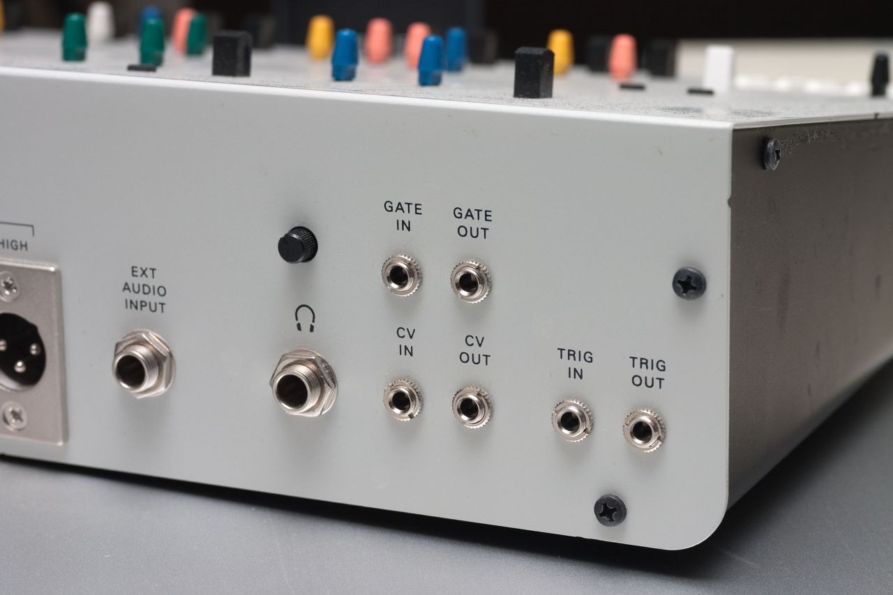
Analog connections with CV/GATE
Before MIDI, the most common way to interface analog synthesizers was analog connections using CV (Control Voltage) and Gate.
With analog synthesizers, the pitch of the sound is determined by the height of the voltage. This voltage is called CV for control voltage. Whether or not to any sound is emitted is controlled by a voltage called Gate.
In early modular synthesizers, each synthesizer component (e.g., low frequency oscillation (LFO), voltage controlled filter (VCF), etc.) can be connected to another component by means of a patch cable that transmits voltage.
Changes in that voltage cause changes to one or more parameters of the component.
This frequently involved a keyboard transmitting two types of data (CV and gate), or control modules such as LFOs and envelope generators transmitting CV data:
- Control voltage (CV) indicates which note (event) to play: a different voltage for each key pressed; those voltages are typically connected to one or more oscillators, thus producing the different pitches required. Such a method implies that the synthesizer is monophonic. CV can also control parameters such as rate, depth and duration of a control module.
- Trigger indicates when a note should start, a pulse that is used to trigger an event, typically an ADSR envelope. In the case of triggering a drum machine, a clock signal or LFO square wave could be employed to signal the next beat. The trigger can be a specific part of an electronic pulse, such as the rising slope of an electronic signal.
- Gate is related to a Trigger, but sustains the signal throughout the event. It turns on when the signal goes high, and turns off when the signal goes low.
by Wikipedia
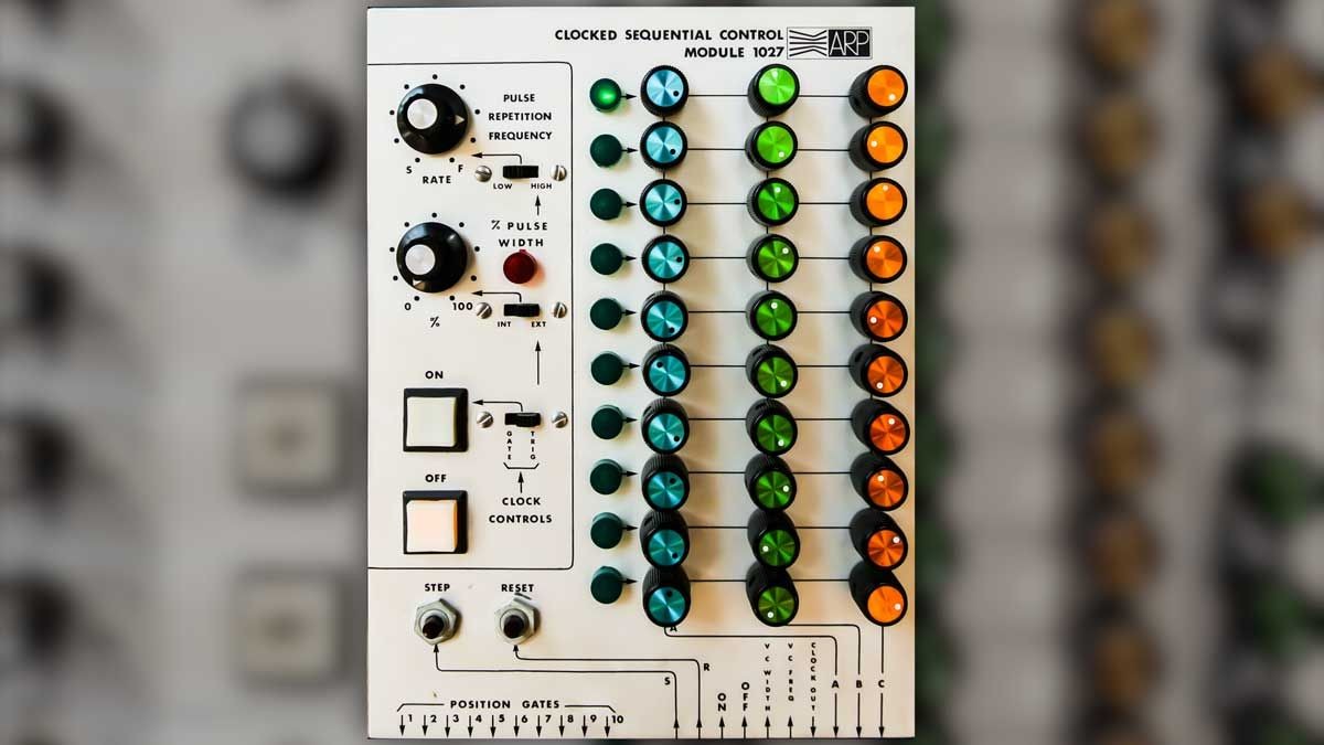
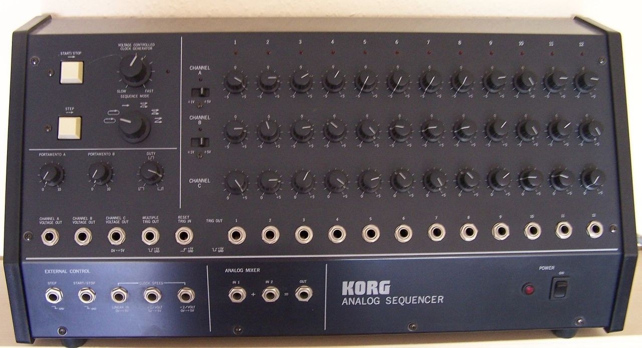
Analog Sequencers
Moog, Buchla and ARP had always included Analog Sequencer Modules in their modular designs.
Within a few years other companies including Roland and Korg were making similar products.

The Challenge with Control Voltages
The problem with Control Voltage was that from the very start there were two different standards.
- Volts per octave was popularized by Bob Moog in the 1960s.
- One volt represents one octave, so the pitch produced by a voltage of 3 V is one octave lower than that produced by a voltage of 4 V.
- Each 1 V octave is divided linearly into 12 semi-tones.
- Companies using this CV method included Roland, Moog, Sequential Circuits, Oberheim, ARP and later the Eurorack standard from Doepfer, including more than 7000 modules from at least 316 manufacturers.
However, other manufacturers have used different implementations with voltages including –5 V to 5 V, 0 V to 5 V, 0 V to 10 V with the B+ possibly on the tip.
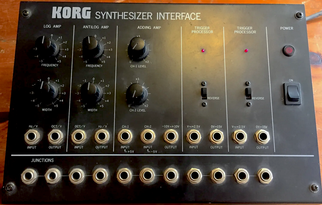
- Hertz per volt was used by most but not all Korg and Yamaha synthesizers, represents an octave of pitch by doubling voltage, so the pitch represented by 2 V is one octave lower than that represented by 4 V, and one higher than that represented by 1 V.
The two implementations are not completely incompatible.
Connecting a Hz/volt keyboard to a volts/octave synthesizer will produce sound, but it will be completely out of tune.
Of course with voltages it was easy to modify things with a few parts and a soldering iron.
At least one commercial interface has been created to solve the problem, the Korg MS-02 CV/trigger interface.
But these interfaces weren’t really intuitive for musicians and there were a lot of cables involved.
The Roland Micro Composer MC 8
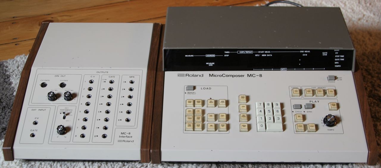
The Roland MC-8 released in 1977 was a seminal product. It was a microprocessor based sequencer that connected to an MC-8 Interface to send out analog voltages. So it it was a hybrid digital and analog system.
It was initially conceived by Ralph Dyck, a Canadian composer and Roland System 100 user.
Ralph went his his local Roland dealer in Canada who introduced him to Ikutaro Kakehachi, the President of Roland.
Kakehachi got Roland engineer Yukio Tamada involved who made the Micro Composer capable of multi-tracking (allowing multiple parts to be played simultaneously). The MC-8 could play eight notes at the same time so it was capable of complex chords.
Tamada-san also integrated the so-called ST/GT method -Step Time for sound length and Gate Time for note length.
This ST/GT concept was later adopted by other Japanese manufacturers.
The Microcomposer is also significant in the development of music production concepts because it was also the first time that a Time Base with resolution of a quarter note was introduced into the world of modular synths.
Many of the ideas that were developed for the Micro Composer would find their way into an industry standard musical digital interface that was on the horizon.
Interview from the Vintage Roland MC-8 Sequencer Archive
In the late 1970s, musicians certainly had virtually no background in computers. What sort of reaction did they have to the “music by numbers” method of programming the MC-8?
Ralph Dyck:
They didn’t like it much except Tomita and Steve Porcaro and Suzanne Ciani.
Steve Porcaro did a lot of musically interesting parts with it.When was the last time you worked with an MC-8, and what sort of production was it?
I think that the last time I used an MC-8 was with Toto, maybe for their album ‘Turn Back’.
The Oberheim System- OB-8, DMX and DSX

Marcus Ryle (who would later design the Alesis ADAT and then go on to found Line 6) was just 19 years old when he got a job at Oberheim in 1980.
He had been studying at UC Santa Dominguez Hills because they had just installed a recording studio with a synthesizer. Tom Oberheim came as a guest lecturer to the college and after a long conversation with Marcus hired him to work at Oberheim alongside Tom and JL Cooper.
Oberheim had just come out with the OBXa which had a 37 pin D-Sub connector with a parallel bus. Soon Marcus was working on the design for the DSX Sequencer.
By connecting an Oberheim polyphonic synth to a DSX and the DMX Drum Machine, you had a complete music system.
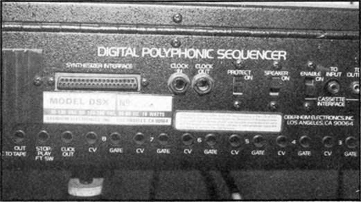
The heart of this system is the DSX sequencer which can control the whole family of Oberheim polyphonics – the OB-X, the OB-Xa and the latest model, the OB-8 via a computer interface. It also has 8 separate CV and gate outputs to control up to 8 analogue synths of the 1 volt per octave variety. It has a capacity of 6,000 notes and is capable of 16-voice polyphony. It can store up to 10 sequences at any one time and there is cassette storage for building up a repertoire of sequences. Each individual sequence can be independently recorded over 10 tracks and there are two recording modes: Real Time (with a 1/192 note resolution) or Quantize which will auto-correct your playing to ½ note (minimum) maximum or 1/32 note (demi-semiquaver) minimum. There is also a programmable metronome with an internal speaker.
by Paul Wiffen for Electronics & Music Maker, Future Publishing
You can even see by the back panel of a DSX Sequencer how intimidating musical instrument interfacing could be in the early 1980s.
Here is a recording from 1983 of what was possible with the Oberheim System.
DCB- Roland’s Digital Communications Bus
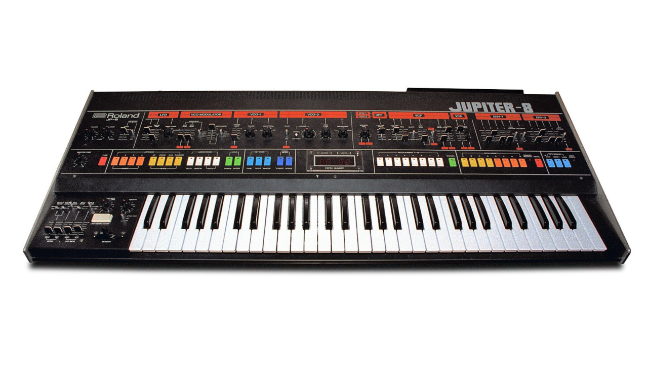
Roland’s DCB (Digital Communication Bus was a proprietary data interchange interface by Roland Corporation, developed in 1981 and introduced in 1982 in their Roland Juno-60 and Roland Jupiter-8 products. DCB only provide note on/off, program change and VCF/VCA controls. The DCB interface was made in 2 variants, the earlier one used 20-pin sockets and cables, later switching to the 14-pin Amphenol DDK connector vaguely resembling a parallel port.
The DCB was a Serial Interface that ran at 31.25Kbps the same rate as MIDI over 5 Pin Din.

Roland Din Sync
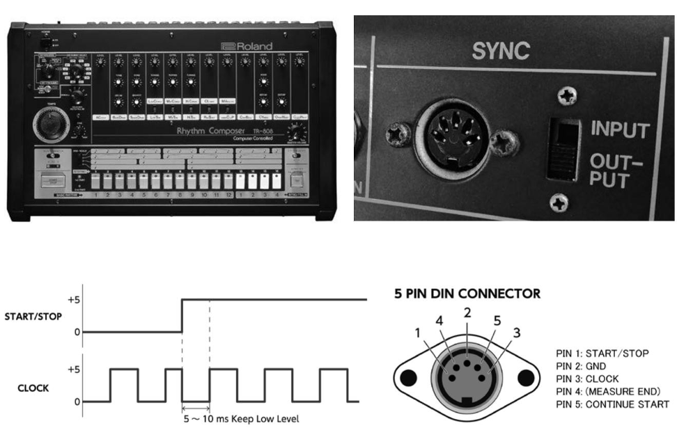
To synchronize their sequencers and rhythm machines Roland developed a proprietary for syncing using a 5 PIN DIN Connector
In 1981, the stage is set for the MIDI revolution
By 1981, multiple companies were working on proprietary digital interface standards including Oberheim, Sequential Circuits, Roland and Yamaha.
But several companies were already starting to worry about the problems these proprietary standards would create.
Customers would be forced to choose one company’s system and be locked into only one way of making music or they would have to spend lots of money on interface convertors to connect gear from different manufacturers together.
A couple of companies started to dream about a universal standard for synthesizers and music production.
In the next chapter of MIDI history, we will finally to tell the full story of how MIDI got started, who helped to make it happen and the challenges that MIDI faced in its early days between 1981 and 1985.